Overview
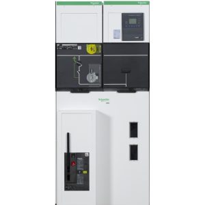
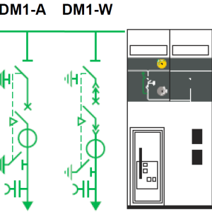
| Introduction | DM1-A & DM1W are part of SM6 product range and called as single section isolation circuit breaker.
This modulator unit is used for MV section of MV/LV substation in secondary distribution system up to 24 kV |
| Application | DM1-A is single isolation circuit breaker unit with fixed breaker, normally used as incoming or outgoing cubicle.
DM1-W is withdrawable single isolation circuit breaker unit and it is also used for incoming or outgoing feeder. This DM1-A or DM1-W is normally installed together in system with other parts of SM6 product range such as |
Main
| Basic Equipment | • SF1 circuit break 630 amp • Three phase busbar 630 A • Disconnector and earthing switch • RI circuit breaker operating mechanism • Enlarge low voltage compartment • Three current transformers • Auxiliary contacts on circuit breaker • CC earthing switch operating mechanism (only for DM1-W) • Downstream earthing switch • Heater 50 W, 220V • Voltage presence indicator |
| Optional LV Control DM1-A | • DM1-A fix LV cable connection • DM1-A plug in LV cable connection |
| Condition Monitoring | • Basic : Thermal sensors (TH110) • Option : Humidity sensors (CL110) |
SF6 Circuit Breaker Cubicles
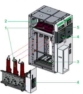
(1) switchgear: disconnector(s) and earthing switch(es), in enclosures filled with SF6 and satisfying “sealed pressure system” requirements.
(2) busbars: all in the same horizontal plane, thus enabling later switchboard extensions and connection to existing equipment.
(3) connection and switchgear: accessible through front, connection to the downstream terminals of the circuit breaker.
Two circuit breaker offers are possible:
SF1: combined with an electronic relay and standard sensors (with or without an auxiliary power supply
SFset: autonomous set equipped with an electronic protection system and special sensors (requiring no auxiliary power supply).
(4) operating mechanism: contains the elements used to operate the disconnector(s), the circuit breaker and the earthing switch and actuate the corresponding indications
(5) low voltage: installation of compact relay devices (Statimax) and test terminal boxes. If more space is required, an additional enclosure may be added on top of the cubicle.
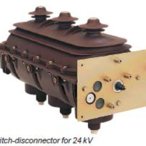
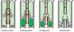
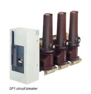
SF6 Circuit Breaker : SF1
Gas tightness
The SF1 circuit breaker is made up of three separate poles mounted on a structure supporting the operating mechanism. Each pole-unit houses the active elements in an insulating enclosure filled with gas to a relative pressure of 1.5 bar (0, 15 mPa) for 24 kV and 2 bar (0,2 mPa) for 36 kV. It satisfies sealed pressure system” requirements and seal tightness is always checked in the factory.
Operating safety
Accidental over-pressures are eliminated by the opening of the safety membrane
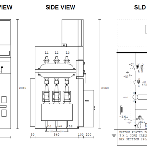
Physical
| Colour | White (RAL 9003) |
| Height | 205 cm – DM1-A/DM1-W |
| Width | 75 cm – DM1-A/DM1-W |
| Depth | 122 cm – DM1-A/DM1-W |
| Net weight | 400 kg DM1-A/DM1-W |
Electrical Characteristics
| Rated Voltage | Ur | kV | 7.2 | 12 | 17.5 | 24 |
| Insulation Level | ||||||
| Insulation | Ud | 50/60 Hz, 1 min (kV rms) | 20 | 28 | 38 | 50 |
| Isolation | Ud | 50/60 Hz, 1 min (kV rms) | 23 | 32 | 45 | 60 |
| Insulation | Up | 1.2/50 µs (kV peak) | 60 | 75 | 95 | 125 |
| Isolation | Up | 1.2/50 µs (kV peak) | 70 | 85 | 110 | 145 |
| Rated voltage | Ur | kV | 7.2 | |
| Breaking capacity | ||||
| Transformer off load | A | 16 | ||
| Cable off load | A | 31.5 | ||
| Rated current | lr | A | 400 – 630 – 1250 | |
| Short-time withstand current | lk/tk^(1) | kA/1 S | 25 | 630 – 1250 |
| 20^(2) | 630 – 1250 | |||
| 16 | 630 – 1250 | |||
| 12.5 | 400 – 630 – 1250 | |||
| Making capacity (50 Hz) | lma | kA | 62.5 | 630 | NA |
| 50 | 630 | |||
| 40 | 630 | |||
| 31.25 | 400 – 630 | |||
Standards & Specification
| IEC Standards | 62271-200 ,62271-1, 62271-103, 62271-105, 62271-100, 62271-102, 61869-2, 61869-3, 60044-8,
62271-206, 62271-304 |
| UTE Standards for SM6-24 | NFC 13.100 NFC 13.200 NFC 64.130 NFC 64.160 |
| EDF Specifications for SM6-24 | HN 64-S-41 HN 64-S-43 |
| SEISMIC Standards for 24 kV | IEEE-693 2005 EN600068-3-3 1993 |
Environmental
| Ambient air temperature | ≤40 °C ≤35 °C on average over 24 hours ≥-5°C |
| Humidity | • Average relative humidity over a 24 hour period, ≤ 95% • Average relative humidity over a 1 month period, ≤ 90% • Average vapor pressure over a 24 hour period, ≤ 2.2 kPa • Average vapor pressure over a 1 month period, ≤ 1.8 kPa.For these conditions, condensation may occasionally occur. Condensation can be expected where sudden temperature changes occur in periods of high humidity.To withstand the effects of high humidity and condensation, such as breakdown of insulation, please pay attention on Civil Engineering recommendations for design of the building or housing, by suitable ventilation and installation. |
| Ambient Air Pollution | No significant pollution by dust, smoke, corrosive and/or flammable gases, vapors or salt. |
| Operating altitude | ≤ 1000 m > 1000 m, a derating coefficient is applied (Please consult us) |
| Solar radiation | No solar radiation influence is permitted. |
| Seismic (24kV & 36 kV) |
• Up to 0.5 g (horizontal) and 0.4 g (vertical) • Class 2 for 24 kV and Class 1 for 36kV • According to standards IEEE-693/2005 and EN 60068-3/1993 for the 24 kV and 36 kV |
| Electro-magnetic compatibility | • Relays: 4 kV withstand capacity, as per recommendation IEC 60801.4 • Compartments: Electrical field: — 40 dB attenuation at 100 MHz — 20 dB attenuation at 200 MHz Magnetic field: 20 dB attenuation below 30 MHz. • According to standards IEEE-693/2005 and EN 60068-3/1993 for 36 kV (please contact us). |
| Temperatures | The cubicles must be stored and installed in a dry area free from dust and with limited temperature variations. • For stocking: from -40°C to +70°C • For working: from -5°C to +40°C • Other temperatures, consult us. |
| Protection Index | • Classes: PI (insulating partition) • Loss of service continuity classes: LSC2A (LSC1 for metering GAM/GBM functions) • Units in switchboard: IP3X • Between compartments: IP2X for SM6-24, IP2XC for SM6-36 • Cubicle: IK08 for SM6-24, IK07 for SM6-36. |
Monitoring
| Continuous Thermal Monitoring | The power connections in the Medium Voltage products are one of the most critical points of the substations especially for those made on site like: • MV Cable connections Loose and faulty connections cause an increase of resistance in localized points that will lead to thermal runaway until the complete failure of the connections.Preventive maintenance can be complicated in severe operating conditions also due to limited accessibility and visibility of the contacts.The continuous thermal monitoring is the most appropriate way to early detect acompromised connection. |
| Easergy TH110 Thermal Sensor | Easergy TH110 is part of the new generation of wireless smart sensors ensuring the continuous thermal monitoring of all the critical connections made on field allowing to: • Prevent unscheduled downtimes • Increase operators and equipments safety • Optimize and predictive maintenanceThanks to its very compact footprint and its wireless communication, Easergy TH110 allows an easy and widespread installation in every possible critical points without impacting the performance of the MV Switchgears.By using Zigbee Green Power communication protocol, Easergy Th110 ensure a reliable and robust communication that can be used to create interoperable solutions evolving in the Industrial Internet of Things (IIoT) age.Easergy TH110 is self powered by the network current and it can ensure high performances providing accurate thermal monitoring being in direct contact with the measured point. |
Current Transformer
| Service Condition | Indoor | |
| Insulation | Dry epoxy resin moulded and treated under vacuum | |
| Highest system voltage | kV | 24 |
| Rated power‐frequency withstand voltage | kV | 50 |
| Lightning impulse test voltage | kV | 125 |
| Rated frequency | Hz | 50 or 60 |
| Rated primary current | A | 10 to 800 |
| Single ratio, double ratio or multi ratio | Single ratio or double ratio on primary taps | |
| Rated secondary current | A | 1 or 5 |
| Rated continuous thermal current | A | 1.2 In |
| Rated short‐time thermal current | kA/1s | * Up to 25 kA/1s ; Up to 40 kA/1s |
| Number of cores | 1 or 2 | |
| Accuracy classes | Measurement : 0.2S ; 0.2 ; 0.5 ; 1 Protection : 10P10 ; 5P10 ; 5P15 ; 5P20 |
|
| Rated burdens | VA | ** 2.5 ; 5 ; 7.5 ; 10 ; 15 ; 30 Different values are available upon request |
| Approx. weights | kg | 27 |
* Rated short‐time thermal current depend on rated primary current, accuracy class & burden
** Rated burden depend on rated short‐time thermal current & accuracy class
Voltage Transformer
| Service Condition | Indoor | |
| Insulation | Dry epoxy resin moulded and treated under vacuum | |
| Connection | Phase to earth | |
| Highest system voltage | kV | 24 |
| Rated power‐frequency withstand voltage | kV | 50 |
| Lightning impulse test voltage | kV | 125 |
| Rated frequency | Hz | 50 or 60 |
| Rated primary voltage | kV | 2.4√3 ~ 22/√3 |
| Rated secondary voltage | V | 100√3 ; 110√3 ; 100/√3 ; 110/√3 |
| Number of secondary windings | 1 or 2 | |
| Rated voltage factor | Un | 1.2 Cont. : 1.9/30 s or 1.9/8 h |
| Accuracy classes | Measurement : 0.2 ; 0.5 or 1 Protection : 3p or 6p |
|
| Rated burdens | VA | * 10 ; 15 ; 25 ; 30 ; 50 ; 75 |
| Approx. weights | kg | 24 |
* Rated burden depend on accuracy class
Packing Units
| Unit Type of Package 1 | PCE |
| Number of Units in Package 1 | 1 |
| Package 1 Height | 230 cm |
| Package 1 Width | 90 cm |
| Package 1 Length | 190 cm |
| Package 1 Weight | 400 kg |
Contractual warranty
| Warranty | 12 Months |